Upper A-Arms
Remove the bolts and adjusting cams from the upper A-arm and pull the arm out of the frame brackets. You may have to wiggle the front cam around to get the bolt past the shock absorber bracket. Check the cam adjustment bracket surface for weld splatter, dirt, or rust, and clean up as needed to avoid affecting the alignment.
Note: If you broke a hard brake line as I did, now is a good time to repair or replace it, with the upper A-arm out of the way.
Remove the old upper ball joint by cutting, grinding, or drilling off the old rivets from the top of the A-arm. I used an angle grinder with a thin metal cutting disc to remove the bulk of the heads, then ground off what was left. You'll be throwing away the ball joint and its top plate. Just don't cut or drill into the A-arm itself.
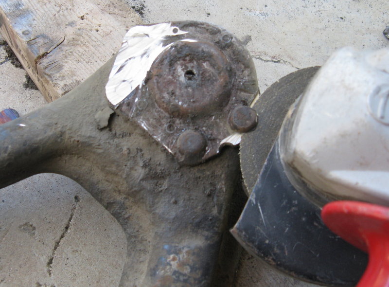
Once the rivet head is off, you should see a thin line around body of the rivet. Punch the rivet as close to the center as possible, then use a 1/4" drill bit to drill down about 1/4". Do not drill into the A-arm. This hole will give the rivet a place to collapse into as you drive it out. Position the ball joint stud on a scrap piece of wood or steel, and the back of the A-arm on a block so the ball joint plate is level. Place a small punch in the 1/4" hole and with a big hammer, hit the punch hard to drive the rivet out. It will probably take a lot of very solid hits, but it will eventually move. Pull off the old ball joint and clean up the mounting surfaces on the A-arm.

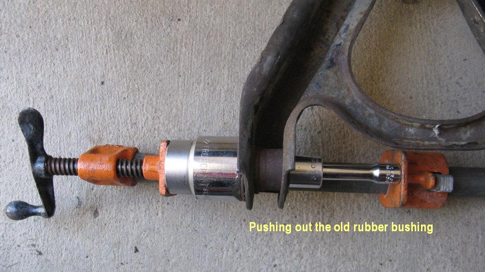
There are a lot of different ways to get the A-arm bushings out, but here's how I did it: Using a hammer and chisel or small crow bar, pop off the metal ends of the upper A-arm bushings by working the tool under the lip of the metal. Try not to bend them since you'll still need one set per arm. Use a screw clamp and a short (about 2") 3/8" socket extension with about a 3/4" socket to remove the old bushings. You want a tool that won't get stuck once the sleeve and bushing are pushed out. There are many other combinations of sockets and tools that can do the job. You'll also need a spacer to give the bushing a place to go, such as a big socket or steel plumbing cap.
First use the back of the socket extension to push out the center sleeve. Save one set of caps and one inner sleeve from each arm for use with the new Urethane bushing.

Once the sleeve is out, turn the socket and extension around and use the 3/4" socket to push out the rubber bushing. Do not damage the outer sleeve on the front of the arm since you'll need to reuse it with the new bushing.
Remove the outer metal sleeve from the rear of the A-arm ONLY. Use a hacksaw to cut the sleeve in half down its center in between the A-arm sides. Do not cut into the A-arm.
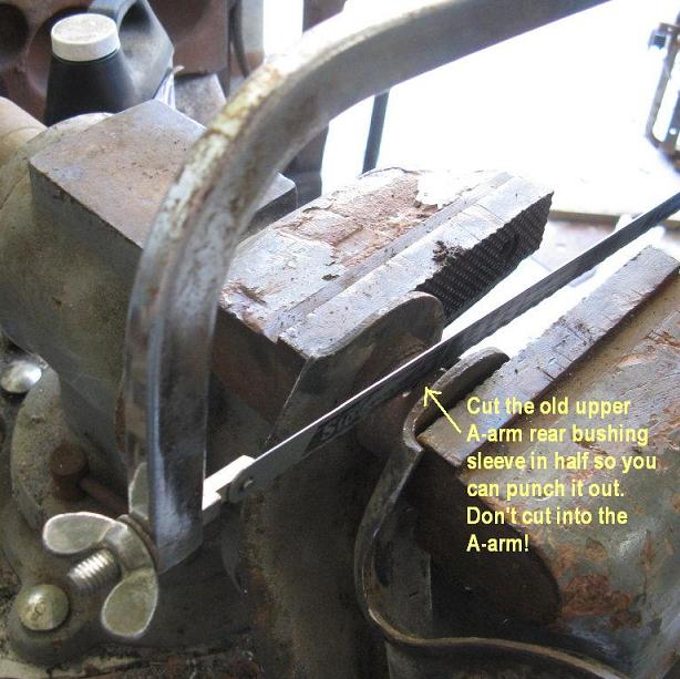
If you get them mixed up, the rear of the upper A-arm is the one with the curved side. Do not remove the front sleeve since you'll need to reuse it for the new urethane bushing.

Use a hammer and punch to deform the cut sleeve and drive it out of the A-arm.

Drive out the other side of the sleeve. If you have too much trouble, try cutting the sleeve again perpendicular to the last cut to give the metal a place to collapse into. Do not cut into the A-arm.

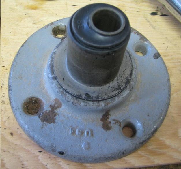
Clean up the rear hole in the arm really well and remove any burrs, rust, paint, or dirt. It may help to lightly sand or file the hole, but don't remove too much metal. Align the new offset bushing in the rear hole of the upper A-arm with the arrow pointing AWAY from the ball joint.

Gary Worobec found that a 1 1/2" iron pipe flange or coupler fits the metal edge of the bushing and makes it easier to press in evenly. Alternatively, put the provided larger metal cap on the big end of the bushing to spread the force and prevent damage to the inner metal sleeve. If you do it that way, be sure to note how the bushing looks from the back side of the A-arm since the cap will cover the arrow. You'll need a spacer to push against while allowing room for the bushing to go through the back of the A-arm, such as a 1 1/2" socket or a big plumbing pipe cap. You must also use a spacer that fits snugly between the arm sides to keep them from deforming. I had a lot of trouble getting these bushings into the arm, mostly because they just wouldn't drive in straight. I alternated between using a big vice and a big hammer, frequently stopping to check and adjust the alignment. If you're hammering, place the arm on a piece of scrap wood to prevent damage. I used a long socket extension through the hole of the bushing as a lever to move it back into line.

Once the new bushing is fully inserted into the arm, put the new small cap on the small end of the bushing and seat it into the inner metal sleeve. The new big cap goes on the big end.
Before installing the front bushing, clean the interior of the old outer metal sleeve on the A-arm. Lubricate the sides of the new urethane bushing with the provided grease. Use a mallet to drive the new bushing into the old A-arm front outer sleeve. Make sure it's completely seated. Grease the outside of one of the old inner metal sleeves and drive it flush into the new bushing. Put one of the old big caps on the big end and the little cap on the little end and seat them into the old inner metal sleeve.
Clean and inspect the old cam assemblies you removed. If the bolt threads are stripped, replace them. Otherwise, you won't be able to torque them properly and will have alignment problems. Apply anti-seize to the bolts and threads.
Guide the upper control arm into the frame bracket and re-install the cam assemblies. The cam bolts should be installed from the center of the A-arms so that the bolt heads are both in the middle of the arm, facing in opposite directions.
Note: It is harder to install the cam bolts this way because the shock mounts are in the way, but makes it easier to get a torque wrench onto the nuts later. You may need to pull the a-arms outwards and separate stuck cams from the bolts in order to insert them into the adjustment slot.
Turn the rear cam bolt so that the A-arm is pulled in as close to the frame as possible. This will move the upper ball joint toward the rear of the coach and provide maximum possible caster.

Adjust the front cam bolt so it's in the middle of the adjustment slot in the bracket. This should set the wheel to approximately 0 camber (plumb vertical), though it won't look like it until after the coach has its wheels on the ground and is driven around a bit.

Torque the cam nut to 80 ft-lbs. Hold a wrench on the cam bolt head to keep the cams from turning.
Place the new upper ball joint plate on top of the upper A-arm mounting hole. Put some red Loctite on the threads of the provided bolts and insert the bolts through the top of the ball joint plate. Use the lock washers and nuts on the underside of the A-arm. Torque the nuts to 20 ft-lbs. Install the new grease fitting into the upper ball joint, snug but not too tight. Seat the rubber grease boot onto the ball joint.

You may also want to spot weld the upper ball joint plate to the top of the A-arm, but this is not required.
© Copyright 2011,2012,2013,2014,2015,2016 K. Bradley
Previous Next