Installing the One Ton Front End Version II

The classic 1973 - 1978 GMC Motorhome is a marvelous
machine. However, as most GMC owners know, the front end is a
weak point of the design. Around 2007, Bill Hubler developed a kit
to retrofit GM heavy duty truck parts onto the GMC motorhome front end.
In 2011, Manny Trovao figured out how to improve the kit and brought the cost down by buying new parts in large quantities. The result is the new Version II One-Ton Front End Kit.
This is a terrific upgrade that solves a lot of problems. Given how difficult
and expensive it is to service the original bearings and how often it
must be done, this is a cost effective solution for that problem
alone. It provides much bigger sealed bearings good for 200K miles.
In addition, it gives you heavy-duty knuckles, ball joints, and CV
joints, bigger brake rotors, reinforced lower A-arms, and a spacer
that moves the front wheels into line with the rear.
These instructions describe how I installed the Version II kit. Mostly. They also include tips from
pros and things I learned that I wish I'd known in advance. Special thanks to the knowledgeable people who provided
advice, encouragement, proofreading, ideas, and extra pictures, and THANK YOU Manny Trovao and Bill Hubler for this great upgrade!
These instructions are available on the web at http://www.machinesoflovinggrace.net/gmc/frontend.
Email suggestions and comments to molggmc at sonic.net.
DISCLAIMER:
THIS IS A WORK IN PROGRESS. I will update it as I get feedback. Please use the most current version.
This copy was published 3/18/2016.
IMPORTANT NOTE: Manny routinely upgrades his kits as he gets feedback. Some of the parts you receive may look different from the ones pictured here.
I will try to keep these instructions updated if there are significant changes.
WARNING: USE AT YOUR OWN RISK!
Working around and under a 6-ton vehicle is hazardous. The instructions are as correct as I can make them,
but I OFFER NO GUARANTEES ABOUT ANYTHING. I have no monetary interest in the people or products mentioned in this document.
Before you start, order these parts:
You'll need right and left front brake
calipers for a 1996 GMC/Chevy Suburban Diesel 4x4 with 8600 lbs GVW
(also referenced in parts catalogs as having 13" rear brake drums). Order "loaded"
or "semi-loaded" calipers so you get all the hardware
required. If you get "semi-loaded" calipers, you'll also
have to order brake pads.
Note: These are NOT the same calipers as the 80mm upgrade to the OEM front brakes.
Some sample part numbers are listed below. Unless otherwise noted, these are loaded calipers (include pads):
- Bendix L55496M & L55497M
- Centric (semi-loaded) 14166019 & 14166020, Ceramic Pads: 30103700 (Note: The Centric calipers I got rubbed on the inside of the Alcoa wheels. I had to grind a little off the rough casting of the caliper body to clear the wheels.)
- Raybestos RC11985 & RC11986
- Wagner Quick Stop L116294 & L116295
- Wagner Sever Duty S116294 & S116295
If you haven't already upgraded these parts, you should also consider getting:
- Sway bar end links: Moog K446
(need two kits)
- Sway bar frame bushings: Moog
K5253
- Tie rods (need 2 of each part):
- Inner end: Moog ES361R
- Outer end: Moog ES412RL
- Center tube: Moog ES2004S
- Shock absorbers (There are a number of choices. Here are two common ones):
- KYB KG-5435
- Bilstein 8460940
If you find the upper A-arm cam
bolts are stripped, order Moog K5266. Specialty Products Company (SPC) 83160 will also work, but the cams are slightly smaller. One kit does both sides of one A-arm, so to replace all you'll need two kits.
The seals on the back of the knuckles have been inspected and determined to be in good condition. There are also
dust shields
on the new axles that fit over the seals for extra protection. If you prefer to replace the knuckle seals with new ones, the NAPA part number is NOS 31504.
Tools
- Maintenance manual for your coach,available online or on DVD if you don't already have one.
- Torsion bar unloader tool, Kent-Moore J-22517-02. Grease the threads of the tool before use.
Note: It is possible to do this work without the torsion bar unloader on most coaches,
but the tool will certainly make it easier. You MUST use the tool if you need to adjust ride height
after the installation. Given that you're installing a lot of new parts and moving things around, your old
ride height settings may not be correct. As of this writing, Manny Trovao has a couple of these tools to lend for installing the kit.
- Lower ball joint puller (Pitman
Tool 27016 from Autozone, about $15 if you can't get it for
free.)
- 3/8" hex
head (aka allen) socket wrench for removing and installing
caliper bolts with a torque wrench.
- 3/8" and 5/8" flare
wrenches for the brake fittings.
- Vise grips, to help with the flare wrenches.
- Two 1/8" x ~1" cotter
pins for tie rod ends if you're not replacing your tie rods. (new
ones come with pins).
- Brake fluid.
- Red Loctite or equivalent for the
upper ball joint plate bolts.
- Penetrating solvent such as a
50-50 mix of Acetone and Automatic Transmission Fluid, or PB
Blaster.
- Brake Cleaner spray solvent.
- Big C-clamp for pulling the
caliper piston into the caliper body.
- A flat scrap of steel to protect
the caliper piston from the c-clamp, and to protect bolts you're
hitting. (I used the same flat piece I have for holding the rear
wheels up when jacking the bogies.)
- Anti Seize lubricant.
- 1/2" - 20 thread cutting die
for cleaning up the threads on the torsion adjusting bolt.
(optional)
- Small wire brush for cleaning dirt
out of threads.
- Putty knife for removing layers of
old dirt and grease.
- Detergent or degreaser for washing
parts (optional)
- Paint for making it pretty (optional).
- Grease for ball joints, tie rod
ends, and A-arm sockets. Many GMCers recommend a synthetic moly
grease such as Valvoline Synpower or RedLine CV-2. May be overkill
for ball joints.
- Grease gun with long flexible tip
for getting at grease fittings ("zerks") in awkward
places.
- A large supply of disposable
gloves and paper towels. The old stuff is really greasy and dirty.
- A pad or piece of cardboard or
creeper board for lying on under the coach.
- An old blanket or some cardboard for setting axle
assemblies on to protect the CV boots.
- Jacks and jack stands capable of
supporting the coach.
- Blocks for the rear wheels and
bogies.
- Container to hold small parts as
you remove them.
- Container to catch brake fluid.
- A big breaker bar socket wrench
and/or a piece of pipe for an extension handle.
- An assortment of sockets,
extensions, and wrenches. Some of the more unusual sockets include:
- 1 1/2" for the old axle nut.
- 1 7/16" (or 36mm) for the new axle nut
(conveniently, the same size as the bogie pin nuts)
- 22mm (or 7/8") for the
spacer bolts (my impact socket was too big for the holes.)
- short 15/16" (or 24mm) socket for the upper ball joint nut
- 1 1/16" (or 27mm) for the lower ball joint nut (same size as Alcoa lug nuts)
- Needle nose pliers for removing
cotter pins.
- Torque wrenches that can do 20 to
180 ft lbs.
- Crowbars, large and small.
- A press, vise, or bar clamp for
pressing bushings.
- 1 1/2" plumbing flange or coupler to makes it easier to press in the upper a-arm offset bushing (optional)
- Big hammer (4 or 5 lb sledge).
- Brass drift punch for driving
things in/out without damage.
- Scrap wood for protecting parts.
- 1/4" or so small punch for
removing rivets.
- Angle grinder/cutter for removing
rivet heads, or 1/2" drill bit if you have no grinder.
- Drill and 1/4" drill bit for
removing rivets.
- Hacksaw with metal cutting blade
for removing the old upper A-arm rear bushing sleeves.
- Rubber or wood mallet for
persuading things to move without damaging them.
- Pressure brake bleeder (optional,
but very helpful).
- A spacer to to fit snugly between the A-arm sides and keep the arms from deforming as you push bushings in/out.
This could be a curved scrap of metal, a few strategically placed sockets, or a couple of scraps and a band clamp.
- Digital carpenter's level for measuring camber and caster. (optional)
- Tape measure for checking toe. (optional)
- Brake line, fittings,
and tools, only necessary if you damage your old lines. It's likely easier to cut back and re-flare the old
line in place and add couplings as needed because those old fittings
do NOT want to come out. If you need them, Autozone rents brake
tools. You'll need a 45 degree double flare tool to fabricate the
ends of 3/16" brake line, and 3/16" pipe line fittings for
the ends. Be sure to slide the fitting on the line before flaring.
Get extra line so you can practice making flares. The materials are
cheap.
Getting Started
- Measure the front and rear ride height while parked on level concrete, and adjust as needed.
- Park the coach in as level a work area as possible.
- Place blocks under the rear bogies both for safety and so they can't change height.
- Block the rear wheels so they can't roll.
- Center the steering and check that the wheels are pointing straight ahead.
- Remove hubcaps and dust caps from the front wheels.
- Clean the ends of the axles and apply a penetrating solvent to the threads.
- Measure and record the front ride height of the coach in your work area.
- Break loose the lug nuts on both front wheels, but do not remove.
- Remove axle nut cotter pins.
- Break loose the axle nuts, but do not remove.
- Raise coach with a jack under the center crossbar member located under the engine.
- Place jack stands under the crossbar at each end and lower the coach onto the stands.
- Remove the front wheels and put them under the frame for safety. Leave the area near the back end of the torsion bars clear so
you can work.
- With a small wire brush, clean off all the exposed threads you can
reach on the parts you'll be removing: the tie rod ends, brake line
fittings, shock mounts, ball joint studs, A-arm bolts, and torsion
bar adjuster bolts.
- Apply a penetrating solvent and let it soak the threads. Also apply solvent to the sockets of the lower A-arms where the front of the torsion bars are seated.
Remove the Old Middle Parts
The point here is to remove everything attached to the upper and
lower A-arms (aka “Control Arms”). The specific order is
not always important, but some ways are easier than others.
Remove the cotter pins from the tie rod end and upper and lower ball joints.
Place a jack under the lower A-arm and raise it to take pressure
off the shock absorber. Remove the upper bolt and lower nut and remove the shock.
Note: Removing the shock first makes it
easier to work on the brake line connection.
Leave the jack under the lower A-arm.
Position a container under the brake line to catch fluid. Use 3/8"
and 5/8" flare wrenches to separate the flexible brake line from
the hard brake line. It may be completely rusted in place and you may
end up breaking the metal line if you flex it too much. If you don't
use flare wrenches, you will almost certainly destroy the fittings. Even with flare wrenches, it can be very difficult.
Note: Vise grips may help keep the flare wrench ends from spreading as you try to remove brake fittings.
Pull the locking tab from the frame
support to release the flexible line.
Remove the nut from the upper ball joint stud and pull off the
bracket that supports the
brake hose. Thread the castle nut back onto the end of the upper
ball joint stud.
Disconnect the sway bar link from the lower A-arm.
If you have a tie rod puller, use it to remove the tie rod end
from the lower A-arm. If you plan to keep the tie rod, don't use a
pickle fork or it will
ruin the rubber grease boot. If you don't have a puller, unscrew the
tie rod nut until it's flush with the end of the stud. Hold a scrap
piece of steel against the end of the stud and use a big hammer to
hit the steel. This should pop the tie rod end out of the knuckle
eye. Remove the nut and disconnect the tie rod. If you are replacing
the tie rods, disconnect the other end and remove the tie rod. If you are not replacing
the tie rods, it helps to unbolt them and swing them out of the way.

With
the tie rod and sway bar link disconnected, you can now turn the
knuckle to more easily get at the caliper bolts. Remove the caliper
bolts with a 3/8" hex
wrench. Remove any other brackets or cable ties holding the
flexible brake line. Slide the caliper off the rotor. If it's stuck,
you may need to use a big C-clamp to retract the piston (see manual).
Wedge a big crowbar between the wheel studs and against the ground
to keep the axle from turning. Remove the axle nut and washer. Remove
the 6 bolts holding the inner CV joint flange to the final drive
output shaft. Adjust the crowbar placement as needed so you can turn
the axle for easier access. I used a long socket extension so I
didn't have to get under the coach. Don't try to remove the axle yet.

Back off the upper ball joint castle nut until it's flush with the
end of the stud. Pop loose the ball joint by using a hammer and drift
to drive on the spindle, and a big crowbar to pry at the top.

While holding onto the knuckle, remove the castle nut and pull the
stud out of the top of the knuckle. Guide the knuckle down so it's
hanging from the lower ball joint.
Carefully lift the axle/CV-joint assembly free of the final drive
flange and pull it out of the back of the knuckle/hub. An extra set
of hands may help here. Set the axle on a padded surface to avoid
damaging the CV joint boots if they are to be reused. You do NOT have
to remove the output shaft or its support from the right side of the
final drive.

Back off the lower ball joint castle nut so it's partly off the
end of the ball joint stud. This will keep the pitman
puller tool from slipping off the stud. Position the tool arms
over the knuckle eye and its threaded rod against the end of the ball
joint stud. Using a close fitting (possibly metric) wrench, turn the
the puller bolt to apply pressure to the ball joint until it pops
free. It takes a lot of force and you may need to also hammer the
stud and/or eye. Once the ball stud is loose, remove the tool and the
castle nut and lower the knuckle and hub assembly off the stud.
Note: If you still can't remove the lower
ball joint, remove the three bolts that hold the disc/hub retainer to
the knuckle. The bolts are behind the disc and a little hard to get to, but shouldn't
have a lot of torque on them. Slide the disc/hub assembly outward off the
knuckle. The manual shows using a slide hammer, but I was able to
just slide if off with a gentle tap on the back. This will remove
most of the weight from the lower A-arm and make it easier to handle while you're working on the lower ball joint.
If you're replacing your sway bar front frame bushings, now is a
good time to do that. (see manual)
Upper A-Arms
Remove the bolts and
adjusting cams from the upper A-arm and pull the arm out of the
frame brackets. You may have to wiggle the front cam around to get
the bolt past the shock absorber bracket. Check the cam adjustment
bracket surface for weld splatter, dirt, or rust, and clean up as
needed to avoid affecting the alignment.
Note: If you broke a hard brake line as I
did, now is a good time to repair or replace
it, with the upper A-arm out of the way.
Remove the old upper ball joint by cutting, grinding, or drilling
off the old rivets from the top of the A-arm. I used an angle grinder
with a thin metal cutting disc to remove the bulk of the heads, then
ground off what was left. You'll be throwing away the ball joint and
its top plate. Just don't cut or drill into the A-arm itself.
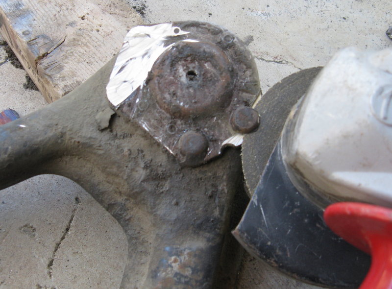
Once the rivet head is off, you should see a thin line around body
of the rivet. Punch the rivet as close to the center as possible,
then use a 1/4" drill bit to drill down about 1/4". Do not
drill into the A-arm. This hole will give the rivet a place to
collapse into as you drive it out. Position the ball joint stud on a
scrap piece of wood or steel, and the back of the A-arm on a block so
the ball joint plate is level. Place a small punch in the 1/4"
hole and with a big hammer, hit the punch hard to drive the rivet
out. It will probably take a lot of very solid hits, but it will
eventually move. Pull off the old ball joint and clean up the
mounting surfaces on the A-arm.

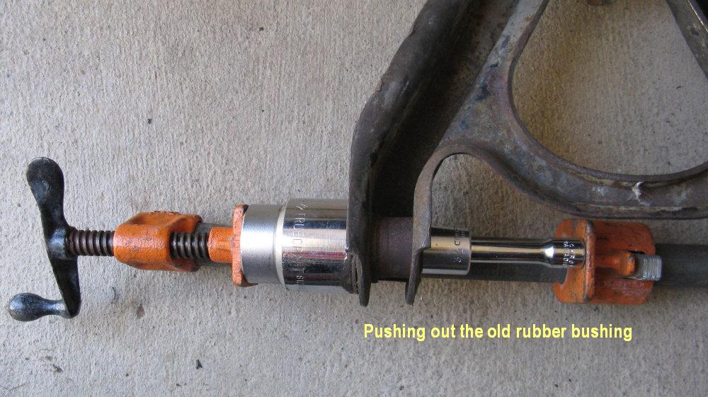
There are a lot of different ways to get the A-arm bushings out,
but here's how I did it: Using a hammer and chisel or small crow bar,
pop off the metal ends of the upper A-arm bushings by working the
tool under the lip of the metal. Try not to bend them since you'll
still need one set per arm. Use a screw clamp and a short (about 2")
3/8" socket extension with about a 3/4" socket to remove
the old bushings. You want a tool that won't get stuck once the
sleeve and bushing are pushed out. There are many other combinations of
sockets and tools that can do the job. You'll also need a spacer to give
the bushing a place to go, such as a big socket or steel plumbing
cap.
First use the back of the socket extension to push out the center
sleeve. Save one set of caps and one inner sleeve from each arm for use with the
new Urethane bushing.

Once the sleeve is out, turn the socket and extension around and
use the 3/4" socket to push out the rubber bushing. Do not damage the outer sleeve on the front of the arm since you'll need to reuse it with the new bushing.
Remove the outer metal sleeve from the rear of the A-arm ONLY.
Use a hacksaw to cut the sleeve in half down its center in between the A-arm sides. Do not cut into the A-arm.
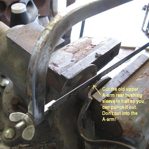
If you get them mixed up, the rear of the upper A-arm is the one with the curved side. Do not remove the front sleeve since you'll need to reuse it for the new urethane bushing.

Use a hammer and punch to deform the cut sleeve and drive it out of the A-arm.

Drive out the other side of the sleeve. If you have too much trouble, try cutting the sleeve again perpendicular to the last cut to give the metal
a place to collapse into. Do not cut into the A-arm.

Clean up the rear hole in the arm really well and remove any burrs, rust,
paint, or dirt. It may help to lightly sand or file the hole, but
don't remove too much metal.
Align the new offset bushing in the rear hole of the upper A-arm with the arrow pointing AWAY from the ball joint.

Gary Worobec found that a
1 1/2" iron pipe flange or coupler fits the metal edge of the bushing and makes it easier to press in evenly.
Alternatively, put the provided larger metal cap on the big end of the bushing to spread the force and prevent damage to the inner
metal sleeve. If you do it that way, be sure to note how the bushing looks from the back side of the A-arm since the cap will cover the arrow.
You'll need a spacer to push against while allowing room for the bushing to go through the back of the A-arm, such as a 1 1/2" socket or a big plumbing pipe cap. You must also use a spacer
that fits snugly between the arm sides to keep them from deforming.
I had a lot of trouble getting these bushings into the arm, mostly because they just wouldn't drive in straight. I alternated between using a big vice and a big hammer, frequently stopping to check and adjust the alignment. If you're hammering,
place the arm on a piece of scrap wood to prevent damage. I used a long socket extension through the hole of the bushing as a lever
to move it back into line.

Once the new bushing is fully inserted into the arm, put the new small cap on the small end of the bushing and seat it into the inner metal sleeve. The new big cap goes on the big end.
Before installing the front bushing, clean the interior of the old outer metal sleeve on the A-arm. Lubricate the sides of the new urethane bushing with the provided grease. Use a mallet to drive the new bushing into the old A-arm front outer sleeve. Make sure it's completely seated. Grease the outside of one of the old inner metal sleeves and drive it flush into the new bushing. Put one of the old big caps on the big end and the little cap on the little end and seat them into the old inner metal sleeve.
Clean and inspect the old cam
assemblies you removed. If the bolt threads are stripped, replace
them. Otherwise, you won't be able to torque them properly and will have alignment problems. Apply anti-seize to the bolts and threads.
Guide the upper control arm into the frame bracket and re-install the
cam assemblies. The cam bolts should be installed from the center of
the A-arms so that the bolt heads are both in the middle of the arm,
facing in opposite directions.
Note: It is harder to install the cam bolts this way because the shock mounts are in the way, but makes it easier to get a torque wrench onto the nuts later. You may need to pull the a-arms outwards and separate stuck cams from the bolts in order to insert them into the adjustment slot.
Turn the rear cam bolt so that the A-arm is pulled in as close to
the frame as possible. This will move the upper ball joint toward the
rear of the coach and provide maximum possible caster.

Adjust the front cam bolt so it's in the middle of the adjustment
slot in the bracket. This should set the wheel to approximately 0 camber (plumb vertical),
though it won't look like it until after the coach has its wheels on the ground and is driven around a bit.

Torque the cam nut to 80 ft-lbs. Hold a wrench on the cam bolt head to keep the cams from turning.
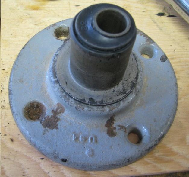
Place the new upper ball joint plate on top of the upper A-arm
mounting hole. Put some red Loctite on the threads of the provided
bolts and insert the bolts through the top of the ball joint plate.
Use the lock washers and nuts on the underside of the A-arm. Torque
the nuts to 20 ft-lbs. Install the new grease fitting into the upper
ball joint, snug but not too tight. Seat the rubber grease boot onto
the ball joint.

You may also want to spot weld the upper ball joint plate to the top of the A-arm, but this is not required.
Lower A-Arms
Before you remove the lower A-arm, clean off a spot on the torsion
bar just behind the A-arm socket and clearly mark the top of the
torsion bar with paint or a marker. This is just to prevent confusion later if anything
shifts or becomes misaligned.
Lower the jack from under the A-arm. Removing the jack will
release most of the load from the torsion bar.
Note: If you can't get the jack out after
lowering it, you can remove it after the torsion bar is unloaded.
If you want to weld on extra support, see
Notes:A-Arm Reinforcement. This is not required, and not something I chose to do.
Install the grease fitting onto the side of the new lower ball joint,
angled toward the rear of the A-arm so you can reach it later. Seat
the lower ball joint grease boot onto the ball joint. There's
a small indentation on the boot that should line up with the grease
fitting.
Clean out the torsion bar socket on the new A-arm and apply a
generous amount of chassis grease to the inside of the socket. Place
the new A-arm near the coach in the correct orientation, ready to
install. Be careful to keep dirt out of the ball joint and torsion
bar socket.
Get under the coach at the rear of the torsion bar and measure how
much the adjuster bolt sticks out of its special square nut. (There
should not be any other nuts or Loctite on the adjuster bolt, though
I ran into both.) The manual says to count turns, but I found it too
easy to lose track while struggling with rusty stuck bolts and
awkward access. Later GM manuals say to measure or "matchstick"
(or "story stick", i.e. mark the length on something else.)
You can also paint the bolt to mark it, but then you won't be able to clean the threads.
Install the torsion bar
unloader tool as described in the manual and tighten it to take
the load off the adjustment bolt. Remove the adjustment bolt and the
big square nut. Unscrew the unloader tool so the small end of the
pork-chop can move down freely a couple of inches below the frame.
This releases all remaining load and makes it easier to get the A-arm
onto the torsion bar. You're NOT trying to remove the torsion bar,
just making it free to move.

Get back out from under the coach. Remove the frame bolts from the lower A-arm and pull the arm out of the frame brackets. A small crowbar may help.
Pull the arm toward the front of the coach to slide its socket off the end of
the torsion bar. A few taps with a mallet may help get it move. Clean the inside
of the frame brackets and the end of the torsion bar and apply fresh
grease.

Note: Now is a good time to inspect the torsion bar and make sure you have a "right" bar on the right, and a "left" bar on the left. Some coaches have had a problem with this, resulting in an inability to properly set ride height. The bars should be stamped on one end with "L" or "R" and have an arrow indicating direction. It may not matter whether the stamp is at the front or rear, but the bars must be on the correct side.
Hold the new A-arm in the same orientation in which you removed
the old one. Place the socket of the new A-arm over the end of the
torsion bar and and seat the socket all the way onto the torsion bar.
Work the arm back into the frame brackets. A small crow bar is useful
for getting the holes aligned. Install the bracket bolts. Install the
nuts but do not torque.
At the back of the torsion bar on the crossmember where the pork-chop is located is a round inspection hole.
Look in this hole to make sure the torsion bar is still fully seated into the pork-chop. If it's not, move
the torsion bar toward the rear of the coach until it's flush with the back of the pork-chop.

Note: If you decide to remove the torsion bar from the pork-chop for any reason, it's probably best NOT to apply any grease between the pork-chop and the torsion bar when you reinstall it. You don't want it to move out of the pork-chop.
Pull up the lower A-arm to about its normal height and put a jack
under it. If you don't know what that height should be, hold up one
of the shock absorbers to where it will mount as a reference.
Install the sway bar links and torque to 15 ft lbs.
Torque the lower A-arm frame bolts to 85 ft lbs.
Note: If you can't torque the bolts,
they're stripped or have the wrong size nuts. That's why you should
torque these here -- so you don't have to unload everything to get
the bolts back out.

While you have it out, clean and inspect the threads of the
torsion adjusting nut and bolt.
If you have a thread cutting tool, use it to
clean up the threads. Apply a liberal amount of anti-seize or chassis
grease to the threads. Use the torsion bar unloader tool to pull the
pork-chop back up so you can fit the square nut into its slot. The
indentations on the square nut face downward and rest on the crossbar
edges. Install the adjusting bolt back to the same measurement it was
before. Remove the unloader tool.
IMPORTANT NOTE: The pork-chop adjuster bolts should be installed so they are equal on both sides. If one pork-chop is held higher than the other, the front load will be unbalanced. This can result in one side being dangerously overloaded, and will affect handling. The rear suspension has a profound effect on the front ride height. When measuring and setting the front height, it is important to first block the rear of the coach to the correct height and then deflate the air bags so they don't apply pressure to the front suspension. When adjusting the front height, try to keep both bolts set close to the same number of turns.
If your kit contains a steering stop bracket, install it on the rear bolt that holds the ball joint to the lower A-Arm. This stop is used with knuckles that were made in 1989-94 because they lack the stop that was molded into later knuckles. The bracket can be mounted above or below the A-Arm. Reinstall the bolt and torque the nut to 45 ft-lbs.

Knuckles and Axles
Clean off final drive output shafts if they have any grease or
dirt on them from your leaky old CV joints.

Carefully guide the new axle onto the lower A-arm, avoiding damage
to the rubber CV boots. Rest the axle on the lower A-arm out of the
way of the lower ball joint so you can get the knuckle on without
running into it.

Clean any rust or dirt out of the tapered holes (eyes) of the
knuckle. Degrease the knuckle eyes and the upper and lower ball joint
tapers with brake cleaner.
Make sure you have the correct knuckle for the side you're working
on. The tie rod steering eye goes toward the front of the vehicle
with the bigger side of the taper facing downward. The caliper
mounting area should be toward the upper side of the rear.

Do not try to reinstall the old brake
hose support bracket on the upper ball joint. There will not be
enough room to install the cotter pin if you use the bracket.
Get some help with installing the knuckle if at all possible. It's heavy and hard to do by yourself. Also, when I got the kit the wheel spacer was already bolted to the hub. If yours isn't, I'd wait to install the spacer until after the knuckle is installed. It's heavy enough as is.
Guide the knuckle assembly onto the lower ball joint stud. Attach
the new ball joint nut and hand tighten. Lower the knuckle so it's hanging from the ball joint. Tighten the lower ball joint nut, but do not torque.
Note: Do not try to re-use the old nut on the new ball joint; it does not have the correct thread. Use the new nut provided with the kit.
Guide the end of the axle shaft into the back of the hub, being
careful not to damage the rubber boots or over-bend the CV joint.
Lift the middle of the axle and rest it on a block of wood or pad
on top of the A-arm to protect the rubber boots from the back of the
A-arm. It's going to slide around around as you wrestle with the
knuckle.

Raise the knuckle and guide the upper ball joint stud into the
upper eye. Install the new nut to hold it in place. You may find it
helpful to slightly jack up the lower A-arm and/or raise the knuckle
with a jack. If you use a jack, put a piece of wood on the jack to
protect the knuckle assembly.
Note: Use only the new nut provided with the ball joint. Do not try to re-use the old nut on the new ball joint stud.

Install the shock absorber before removing the jack supporting the knuckle. This will keep the assembly from dropping too much and potentially damaging the CV boot while you're turning the axle in the next steps.
Remove the wood block from under the axle. Align the bolt holes on
the inner CV joint with the ones on the final drive output shaft.
Install 6 new CV joint bolts and lock washers on each side. The
shorter set of bolts go on the driver's (left) side of the coach so
they won't interfere with the final drive housing. Thread the bolts
in by hand to avoid cross threading.

Wedge a crowbar between the wheel studs and the ground to keep the
shaft from turning. Apply loctite to the inner CV joint bolts and torque them to 55-58 ft lbs. (The manual states these should be torqued to 75 ft-lbs and replaced with new ones if they are removed. However, that exceeds the recommended torque for ASTM Grade A574 bolts, which are stronger than Grade 8.) A long socket extension helps. Turn the axle as needed to access the bolt heads; a helper to work the crowbar is useful here.

Place the big washer on the axle shaft. Install and securely tighten the new
axle nut, but do not torque. It's easier to torque later when the weight of the coach is on the wheels.
If it's not already installed, align the holes in the wheel spacer over the studs on the rotor and guide it into place. Use the 8 nuts provided in the kit to hold it on. Torque the nuts to 120 ft-lbs.
If the spacer was installed previously, check the torque of the nuts. Remove the crowbar.
Torque the new upper ball joint nut to 40 ft-lbs. You'll need a really
short socket to get between the nut and the CV boot. Do not try to re-use the old nut on the new ball joint.
Note: I couldn't find any way to move the
CV joint enough to make this any easier and couldn't fit a 1/2"
torque wrench and regular socket. I ended up using a regular 3/8" socket wrench. Since the tie rod end nuts require about the same torque,
I used them as a reference to feel the force needed on the 3/8" wrench.
Install the cotter pin in the upper ball joint stud and bend the
ends of the pin so that it can't damage the outer CV boot. It may be
difficult to insert the pin due to the thickness of the knuckle eye.
Try curving the cotter pin to get it through the hole. Do not back
off the nut to install the cotter pin.
Torque the lower ball joint nut to 100 ft lbs. Install the new
cotter pin and fold back the ends. Do not back off the nut to install
pin.
Use a grease gun to lubricate the upper and lower ball joints
through their grease fittings.
Note: If you have trouble getting grease
into them, remove and inspect the grease fitting. It may be too long
and running into the interior joint or just installed too tightly. Back it off and try again.
Brakes
Remove the caliper mounting bolts and push out the inner sleeves.

Apply silicone brake grease to the inside of the outer sleeve.
You're trying to fill the center void between the inner and outer
sleeves, in between the outer sleeve o-rings.

Put the inner sleeves back in. Apply a little grease to the
caliper bolt body (but not the threads) and put the bolts back into
the sleeves.
To install the brake pads onto the calipers, insert the spring on
the back of the inner pad into the caliper piston and push down on
the pad until it lies flat against the piston.

Put the outer pad in place and pull the two spring arms into the
indentations on the outside of the caliper body.

Turn the knuckle so that it's easier to get at the back of the
caliper mount.
Note: If you can't turn the knuckle, try
jacking the lower A-arm up a little higher.
Determine which caliper is for the right side, and which is for
the left. The bleeder fitting on the caliper should be at the top
when the caliper is mounted on the knuckle.

If you can't fit the caliper and pads onto the brake rotor, pull
off the inner pad and position a scrap piece of steel against the face
of the piston. Use a C-clamp to pull the piston into the caliper, but
don't pull the piston in past its rubber ring. Reinstall the inner
pad and try again.

Position the calipers on the knuckle and screw in the caliper bolts by
hand to avoid cross threading. Hold the caliper so there's an even
gap between both ends of the caliper body and the knuckle slot. The
gap should be between 0.13 and 0.30 mm on each side. (A piece of
copier paper is about 0.1mm thick, so two pieces of paper can be used
as a spacer while you install the bolts.) Tighten the caliper bolts
and torque to 28 ft-lbs with a 3/8" hex wrench. Check that the gaps
are still correct and adjust as needed.

The flexible brake hose end fitting has an offset to it. It can be
mounted with either face to the caliper depending on your
installation. Figure out how you want to route and support the brake
hose. One solution is to drill a 1/8" hole in the edge of the
upper A-arm for a cable tie. My knuckles had some threaded holes I
chose to use, but not all knuckles have these holes. Move the knuckle
back and forth to its extreme positions to make sure the hose can
move freely. The hose should be protected from damage and have no
sharp bends in any position.

Your calipers should each come with a pair of copper washers. These go
on either side of the brake line fitting where it attaches to the
caliper to prevent leaks. Attach the hose to the caliper with a banjo
bolt and the copper washers. Tighten the banjo bolt until snug.

Using the 3/8" and 5/8" flare wrenches, carefully attach
the new flexible line to the hard brake line fitting. Install the
clip to hold the brake line to the frame bracket. I chose to leave
the new clip on the flexible hose fitting and re-use the old clip.

Flush the front brakes as described in the manual. If you don't
have a pressure bleeder, be sure to place a board under the brake
pedal to avoid pushing down too far and damaging the master cylinder.
Check all the brake fittings for leaks. Tighten as needed.
Clean the brake rotors with brake cleaner and paper towels.
Once both brakes are installed and bled, pump the brake pedal to
seat the pads against the rotors. Do not try to move the vehicle if
you have a low pedal problem.
Tie Rods and Shocks
If you're replacing the tie rods, lubricate the center threads
with chassis grease or anti-seize. Adjust the new tie rod assemblies so they
match up with the old ones. The tie rod ends should be threaded into the
center tubes evenly, with the same number of threads showing on each side of the
tube. The right side tie rod assembly (inner end, center tube, and outer end) should be the
same length as the left side assembly. When tightening the clamps, the gap in the
clamps should NOT line up with the slot in the center tube; see the manual for details.
Torque the tube clamp bolts to 20 ft-lbs.

The old tie rods were mounted with the outer stud facing down into
the knuckle. On the new knuckles, the eye is a little higher and the
taper is reversed, so the tie rod stud must face upward. You must
either reverse the direction on the outer (longer) tie rod end, or
swap the left and right tie rods.

Degrease the tie rod tapers and mounting eyes with brake cleaner.
If you're replacing the tie rods, hold the new tie rod assembly so the
longer end is toward the knuckle and the shorter end is toward the coach.
Insert the stud of the outer (longer) tie rod upward into the new knuckle
steering eye and thread on its nut. Install the inner (shorter) tie
rod end onto the steering arm with the stud pointing toward the front
of the coach.

Torque the nuts to 40-50 ft-lbs. Install new cotter pins and fold
back the ends. Do not back the nut out to install the pin.
Note: It may be difficult to get the
outer tie rod cotter pin inserted due to the thickness of the knuckle
eye. Curving the cotter pin may help.
Lubricate the tie rod ends through their grease fittings. If you
can't get grease to go in, check the grease fittings.
Work the lower shock absorber eye onto lower control arm shock
mount and install the nut. You may need to jack the A-arm up or down
to get the shock inserted. Slide the upper end of shock absorber into
the frame bracket and install the bolt and nut. Torque the nuts to 90
ft-lbs
Almost Done
Reinstall the wheels. Tighten the lug nuts to the extent possible with the
coach off the ground.
Raise the coach and remove the jacks stands. Lower the coach to the ground.
Torque the axle nuts to 170-180 ft lbs. There is no cotter pin on
the new axles.
Torque the wheel lug nuts per specs, depending on what wheels you
have.
Drive the coach around a little bit to settle the parts. (Go easy
on the new brake pads.)
Re-check the axle and lug nut torques.
If you're not comfortable aligning the coach yourself, you should still check and adjust the ride height as described in the manual. Also check that the wheels are approximately parallel as described in the
Alignment section of this document.
Re-install the dust caps, and take it to an alignment shop. Tell them you want 0 toe, 0 camber, and as much caster as you can get with the caster equal on both sides. For maximum caster, the rear adjustment cams should usually be left as close to the frame as possible.
Note: The alignment and ride height may take substantial driving to settle to their final positions. This may mean miles of driving, not just a few blocks. You should periodically re-check and re-adjust until everything stabilizes. It may be more effective for you to do the alignment yourself than to have to keep taking it to an alignment shop, especially if it's a shop you don't know and trust.
Alignment
GMC Motorhomes can be aligned using simple tools. Done carefully, many people report getting better results than alignment shops provided. While there are endless variations of tools and techniques, the procedure given below is the simplest, cheapest effective version I could derive. If your coach has a bent frame or suspension issues, it will probably not be sufficient.
For a more complete alignment kit and recommendations on good but inexpensive digital levels and gauges, see the article by Jerry Work in the GMC Motorcoach section of his website. Special thanks to all the very helpful, knowledgeable people who contributed to this document.
If you have just installed the new front end, the adjustment cams should initially be set with the rear cams as
close to the frame as possible,
and the front cams approximately
centered in their slot with the cam plates above the bolts.
This is just a starting point, but should provide close to maximum caster and 0 camber.
Check that the tire pressure on all six wheels is correct.
The water and fuel tanks should be filled to the levels at which you normally travel.
Check that the front wheels are roughly parallel by measuring from a good tread at the front and rear of the wheels. Small changes in tie rod length have big consequences at the wheels, so they may be significantly out of alignment. If needed, adjust the tie rods as described below so you can drive the coach safely. You'll be checking and adjusting this more carefully later.
Drive the coach to settle the suspension and then park it on a level paved surface, preferably concrete. The wheels should be pointing straight ahead.
When doing an alignment, always check and adjust in this order: 1) ride height, 2) caster, 3) camber, 4) toe. Re-check all measurements after driving the coach. It can take many miles of driving before everything has settled properly. Since you want maximum caster, you can cheat a little by setting the cam bolts for maximum caster as described above and then worry about the other settings.
Check and adjust the ride height as described in the manual using the unloader tool.
This should be done on a level concrete surface because asphalt surfaces are usually not flat enough to get an accurate reading. Block the rear of the coach to the correct height and release the air bag pressure to prevent the rear suspension from compensating for changes to the front suspension.
The ride height should be 13 1/8" +/- 1/4" to the top of the slot located behind the front wheels, and 11 11/16" +/- 1/4" to the top of the slot behind the rear wheels. One inch of ride height equates to roughly six turns of the adjustment bolt.
Once you have figured out what change in height is needed, it is very helpful to jack up the front of the coach at the center frame member under the engine to take up most of the front end weight. This saves both you and the tool from having to work so hard against the weight of the coach. For safety, always be sure to put jack stands or blocks in place before getting under the coach. In order to keep the front weight balanced correctly, both adjustment bolts should be kept approximately the same number of turns so that the pork-chops are held at equal heights. If one pork-chop is higher than the other, the weight will shift to one side. This can dangerously overload the tires and cause handling problems even though the ride height may seem correct. Although uneven loading can also be a result of interior weight distribution or, very rarely, a weak torsion bar, one sign of an unbalanced front end is that the rear airbag on the side opposite the overloaded front tire consistently requires more air pressure than the other side. To keep the front weight balanced, whenever you adjust one pork-chop bolt up or down, count the number of turns and make the same adjustment to the other side.
Note: If you have non-stock wheels or tires, you may need to adjust the ride height to compensate for the difference in the radius of the wheels. Stock sizes are OEM wheels with 8.75/16.5 tires, or 16" wheels with LT225/75R16 tires. These are usually about 29.5 inches in diameter though there is variation between brands.
Alignment work is best done with the wheels resting on turn plates, but anything that allows the wheels to slide more easily will work. Some examples are metal or plastic plates with grease in between, sheet metal, floor tiles, several layers of plastic sheeting, or garbage bags with a little oil or water inside.
Center the steering by turning the steering wheel all the way to the left, then all the way to the right while counting turns. Divide by two and move the wheel back this number of turns.
Caster is defined by the relationship between the upper and lower ball joints. The lower ball joint is in a fixed position, so the only adjustment we have is to move the upper ball joint. The further to the rear the upper ball joint is set, the greater the caster. Camber is the amount the wheels tilt in or out at the top. We measure caster indirectly by measuring the change in camber when the wheels are turned to specific angles.
For our coaches, we want as much caster as possible and it should ideally be the same on both sides, but the actual numbers are not very important.
Measure camber either with a caster/camber gauge,
or by using a digital level or angle gauge on the face of the wheels.
Having the dust caps off make this easier. If you're using a level, you'll need the wheels oriented so you can place it vertically in between the lug nuts.

You can also make a jig so you can check camber regardless of the lugs or caps, such as the simple one shown below, or
the ones shown on the photo site here or
here.

Check the accuracy of a digital level by turning it around end for end on a level surface and re-checking the reading. It should produce consistent results. Some levels can be recalibrated.
To compare caster on the right and left sides, center the steering wheel and then turn it one complete turn to the left. This will turn the wheels approximately 20 degrees. Using a digital level or gauge, measure the camber of one wheel. You can calculate the angle changes, but it's much easier and less confusing to let the gauge do the work.
Hold the gauge to the flat face of the wheel and push the zero button on the gauge.
Keep track of exactly where you placed the gauge on the wheel so you can do it again. Now turn the steering wheel back to center and then one complete turn to the right. Measure the same wheel in the same place to get the change in camber. Repeat the procedure for the other wheel.
The measured change in camber is a fraction of caster and should be close to equal on both sides. On most coaches, the passenger (right) side has less maximum caster than the driver (left) side. You will need to reduce the side that has more caster to match the other side. How close they need to be is debated. Caster and camber will cause a pull toward the more negative set side of the vehicle, so you can use these settings to compensate for road crown or other conditions.
If you want to measure the actual caster instead of just the relative caster side to side, you'll need to be more exact in the angles you turned the wheels.
Multiply the change in camber by a fixed amount according to the angle you used.
For example, if you turned the wheels 20 degrees left and then 20 degrees past center to the right (40 degrees total), multiply the change in camber by 1.43. If you used 15 degrees, multiply by 1.91.
Camber and caster are both adjusted by moving the upper A-arm cam bolts in their slots. To maintain maximum caster, all camber adjustments should be made with the front cams only. To maintain a set caster however while adjusting camber, move both the front and rear cams an equal distance in the same direction. For example, to make the camber more positive while maintaining the same caster, move both the front and rear cam bolts outward from the frame by the same amount.
Adjust the wheels as close to plumb (0 camber) as possible, or very slightly negative (tilted in toward the coach at the top). If negative camber is used, the right side should be slightly more negative than the left. For example, left = 0, right = -1/4 to -1/2 degree, or left = -1/2, right = -1 degree. Once you've got the right settings, torque the cam nuts to 80 ft-lbs while holding the bolt head to keep the cams from moving.
Toe is determined by measuring how parallel the right and left wheels are to each other.
Put a mark on the rear of each tire as high up as allows a tape measure to run under the coach without touching anything but the tires. You want as precise a mark as possible, so use a thin line on a piece of masking tape or the edge of a sharp tread and mark it clearly on both tires so you can easily find it again.
It helps to measure starting at the 1-inch mark on a tape measure rather than the end since it's easier to see and usually more accurate.
Measure the distance between the marks on the right and left tires. Also measure the distance from the mark to the ground. Roll the coach straight forward until the marks on the rear of the tires come to the front at the same height as they were in back. Measure the distance between the marks on the front of the tires. If the measurement is the same plus or minus 1/16th inch, the toe is correct.
If needed, adjust toe by loosening the clamps on both tie rods and turning the center sleeves. It doesn't take much to make big changes at the wheels.
The right and left tie rod assemblies should both be adjusted so they are kept as close to the same length as is possible.
Before you re-tighten the clamps, move the tie-rod end ball joints all the way in the same direction. This is to keep them from binding when in normal steering range. When adjusting the tie rod lengths, the gap in the clamps should NOT line up with the slot in the center tube. Torque the tie rod clamp nuts to 20 ft lbs.
Drive the coach and re-check and re-adjust as needed. This may take several miles and repetitions before everything settles into a stable configuration.
If after driving the coach you find your steering wheel is not centered, you can fix it easily if you have an adjustable drag link. If not, the tie rods can also be used to center the steering wheel. For details see http://www.bdub.net/center_steering_wheel.html .
Additional Notes
Extra Reinforcement of the Lower A-Arms
Though not required, you can weld on extra reinforcement to the A-Arms. Here are some pictures and ideas courtesy of Gary Worobec.
Again, not required. I didn't do any of these changes and have had no problem.
Add extra support to the shock absorber mount on the lower A-arm.

Add extra bracing to the lower ball joint mount on the bottom of the lower A-arm.

Separating the Lower Ball Joint Without
a Puller
You'll need to use the tension between upper and lower A-arms to
help pull apart the lower ball joint, so must do this earlier in the
process while they're still connected. Remove the cotter pin on the
lower ball joint and back off the nut until it's flush with the end
of the threaded stud. Place a jack or block under the A-arm for
safety in case the threads strip, but don't apply pressure to the
A-arm. Hold a big heavy weight (like an 8 or 10 pound sledge hammer)
against once side of the lower knuckle eye. Use a smaller (4 or 5
pound) hammer to hit the other side of the eye. This should pop the
joint loose. I had no success beating the joint apart, but include it
here for completeness since more than one person mentioned it.
Kit Parts Reference (Courtesy
of Manny Trovao)
© Copyright 2011,2012,2013,2014,2015,2016 K. Bradley